Mike Tukea, Andy Taylora, Anne Roquesa - Finsbury (Development), United Kingdom
Christian Maulb - RedLux Ltd, United Kingdom
Artificial hip replacement joints have been in use to treat osteoarthritis and rheumatoid arthritis for decades. These devices consist of a metallic/ceramic ball articulating against a polyethylene or metallic/ceramic hemi-spherical cup. However, these artificial joints do wear and their clinical performance starts declining after 10 to 20 years of successful use. In the case of hard-on-hard bearings, the wear depth and volume remain very small and their measurement has remained a challenge to current technologies.
A novel device, the non-contact RedLux Artificial Hip Profiler, which is based on the chromatically encoded confocal measurement method, has been developed so that these joints can be measured accurately, reproducibly and in a short timescale. The system outputs the component radius for the unworn part, the linear depth of wear and also provides the wear volume.
The design principles are presented and the capability of the equipment to measure worn parts, with linear wear between a few microns and tens of microns is hereby characterised, and correlated with laser micrometer diameter measurements, roundness measurements of linear wear and gravimetric wear assessment.
The Artificial Hip Profiler is capable of measuring spherical bearing surfaces with a resolution of 20 nm. The correlation to benchmark methods for the three parameters considered is very high, with correlation coefficients of 1.02 and 0.95 for the linear and volumetric wear respectively. The R values were 0.988 and 0.996 respectively.
Keywords: Artificial hip joint, linear wear, volumetric wear, optical CMM
* A version of this article was published in Precision Engineering 34 (Oct 2010), pp 777 – 783
An artificial hip joint is a ball-and-socket joint that can replace the arthritic human hip. The spherical head of the femur (thigh bone) moves inside the hemispherical socket of the pelvis. This movement at a rate of typically 1 – 2 million cycles per year leads to wear within the articulation 1.
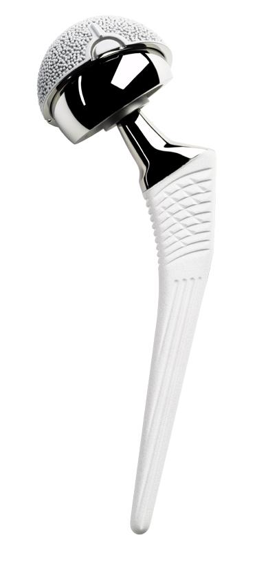
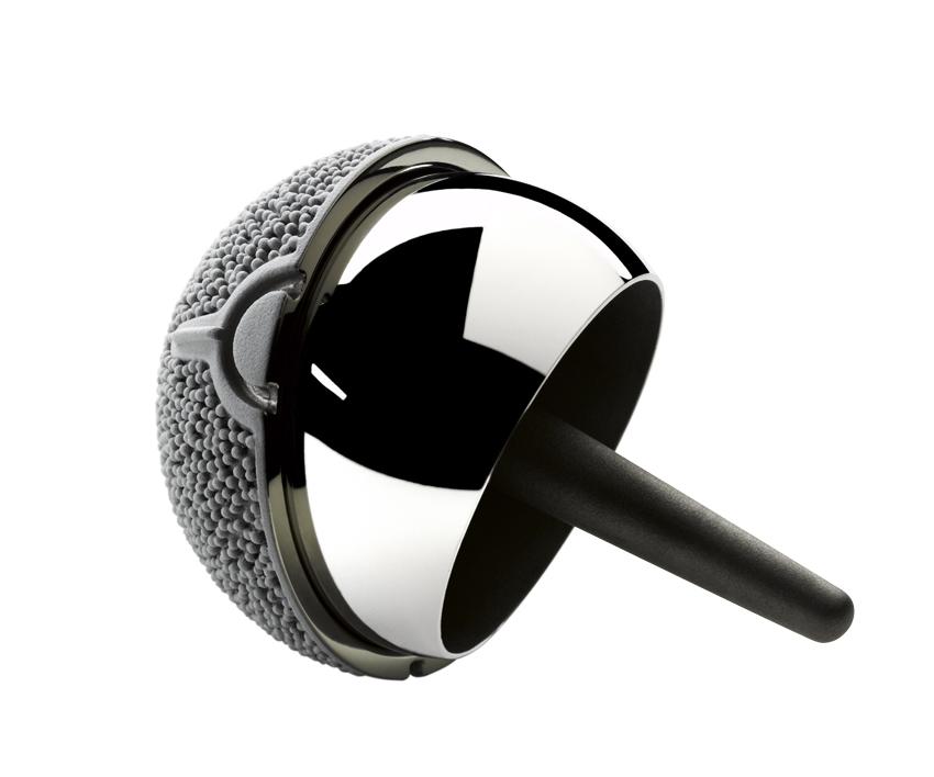
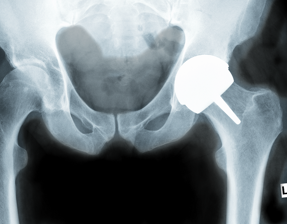
When replacing a worn hip joint, the most likely surgery would involve a femoral stem being inserted into the femur (thigh bone), and a modular head being placed onto the stem via a Morse taper connection 2,3. A hemispherical cup is fitted into the reamed pelvis bone, so that the head can articulate inside the cup and replicate the standard kinematics of the joint (Figure 1 left).
Various material combinations have been used, in an effort to reduce wear at the articulating surfaces and to improve the longevity of the replaced joint 4,5. Metal or ceramic balls articulating against ultra-high molecular weight polyethylene cups with ball diameters of less than 32 mm have been the combination of choice since the 1970s 6 .
With younger patients undergoing joint replacements, ceramic-on-ceramic bearings with ball diameter of less than 32mm have recently gained in popularity 7-9. Both types of device use a relatively small diameter ball compared to the original, human joint, due to the need to reduce sliding distances in the former case, and due to manufacturing limitations in the latter. Both types of device are associated with a dislocation risk, more particularly in the young active patient 10-12.
Metal-on-metal devices have also been used historically with diameters up to 42 mm. This type of device was re-introduced in the 1990s with diameters up to 58 mm to better mimic the patient joint and reduce dislocation risks, and with the bone preserving option of a resurfacing device (Figure 1 centre, and right) 5,13,14.
 |
 |
 |
Successful historical metal-on-metal devices, such as the Ring or McKee Farrar devices, have been reported to achieve linear wear rates as low as 2-10 µm per year 15-18, after up to 25 years of use. Some current metal-on-metal artificial hip joints may have a similar life expectancy as they were designed to emulate these successful devices, although some concerns remain about systemic effect of elevated metal ion levels 14,19-23.
Key to an improvement in the longevity of a bearing is the understanding of its failure. With linear wear rates as low as 2 microns per year 24, this in turns relies on a method of qualifying and quantifying the wear generated on these devices.
The present paper describes a new methodology for 3D volumetric wear measurement, the RedLux Artificial Hip Profiler, and compares the measurement results to established techniques, such as gravimetric and roundness measurement.
In order to simulate wear on hip replacement devices, gait simulators have been developed and wear testing is commonly performed to standard ISO 14242. These simulate up to 10 million cycles of gait activity, and the wear is measured gravimetrically24-27. However, in these simulators, everyday activities other than gait (such as sitting on or rising from a chair or going up and down stairs), and any other, less frequent activities (such as sports) are mostly ignored. The under-estimation of wear by simulators is all the more relevant to younger patients where 10 millions cycles of load may only represent a few years of life 1.
A more accurate method of assessing wear of bearing devices is to assess the components after they have been used in service. Metal-on-metal retrievals for first and second generation devices have been analyzed for wear using coordinate measurement machines (CMM)15 or roundness machines17. The use of non-contact techniques such as laser profilometry and white light interferometry techniques have also been attempted, but with less success due to the space limitation and requirement for data stitching. The most common techniques currently used to assess hip joint bearings wear are reviewed below.
As the hip joint wears, material is eroded from the surface of the ball and cup. This loss of material can be measured by weighing the components before and after the wear process. This alone presents a technical challenge for larger diameter low wearing metallic devices, as the gravimetric changes through wear for these devices are in the order of only a few milligrams for components weighing typically 200 g28-30. To detect these changes reliably is difficult, even for high performance scales.
Indeed, because of possible contamination from the fluids surrounding the joint and the extremely low wear rate of hard bearings, gravimetric methods generally show an increase in mass in the early wear period, before showing a decrease in mass. Correction factors have to be applied to compensate for this error31. The gravimetric method cannot give information on the shape of the wear patch and can only be used on joints that are being evaluated in wear simulators. Implanted components are not suitable for gravimetric measurement, because the exact original weight is unknown and bone ingrowth as well as protein deposits can distort the measurement significantly.
A better way of measuring wear uses a roundness instrument to measure deviations in roundness. This is a two dimensional method that gives the user information from a trace taken around the surface.
Roundness machines can measure deviations from a circle with a resolution of typically 10 nm, and the original unworn part of the trace is compared with the worn ones. Thus the linear wear of clinical retrievals can be evaluated17,24. The roundness instrument is well suited to measuring linear wear, provided enough measurements in various planes around the joint are made and the deepest point of the wear scar is found. Kanada32 calculated that for a ball of up to 38 mm (1.5”) in diameter an average of 9 measurements are required, while for a ball above 50 mm (2”) in diameter, 18 or more measurements may be necessary to fully characterise its roundness. 3D reconstruction of the surface and the estimation of volume wear requires further measurements and assumptions and can be very time consuming17.
Coordinate measuring machines (CMMs) have also been used to measure wear on artificial hip joints15,25,33. A coordinate measuring machine gives a three dimensional representation of the joint by scanning the surface with a stylus. The CMM can scan the whole spherical area of a hip joint, but it has a lower resolution, when compared to a roundness instrument, and is considerably slower as about 400-4000 points are typically necessary 15,33.
To overcome the limitations of the techniques described above, a new form measuring instrument has been developed. The RedLux Artificial Hip Profiler (RedLux Ltd, Southampton, UK) combines the high resolution of the roundness instrument with the high coverage of the CMM, while using an automated, non-contact sensor for increased speed of measurement.
It is capable of scanning the surface of spherical objects. Unlike other optical instruments, it can scan the whole bearing surface of an artificial hip joint in a single measurement taking only a few minutes. This compares to CMM measurements that take a minimum of 20 minutes for high accuracy measurements (~4000 points) 34,35. The resulting cloud of points measured by the AHP is the raw data, and describes the form of the sphere in 3D with a resolution of 20 nm.
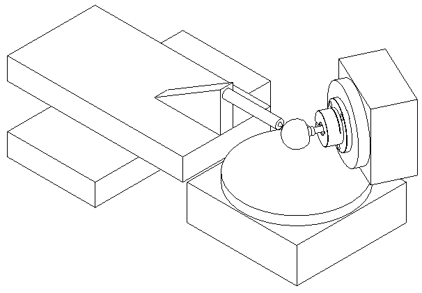
The instrument is a 4-axis optical CMM, as shown in Figure 2. It consists of two linear and two rotary axes, all of which utilise air bearings to achieve superior accuracy of motion. The two rotary stages carry the head or cup and the linear axes carry the sensor. All axes utilise optical encoders and linear or brushless motors.
The sensor was chosen to allow the measurement of artificial heads as well as cups. It is a point sensor, based on the chromatically encoded confocal measurement36, which has previously been successfully applied in the semiconductor, automotive and optical industries among others37,38.
With this sensor, the lens error commonly known as chromatic aberration is used to measure the distance to an object. The axial position of the focal point of an uncorrected lens depends on the colour (wavelength) of the light to be focussed. In the visible spectral region, the focal distance for blue light is shortest while it is longest for red light. The focal points of the other colours are located in between. Depending on the distance of the target from the focusing lens, light of just a very small wavelength region λ1 is focused on the target’s surface (Figure 3).
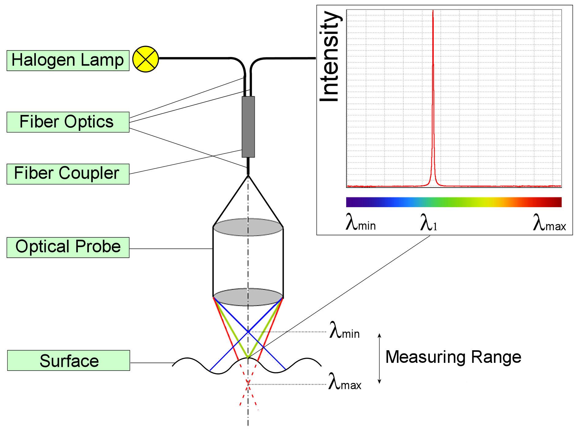
The focusing lens is also used to receive the backscattered light from the target’s surface and to focus it into an optical fibre and later a spectrometer. The wavelength scale of the spectrometer is calibrated versus the distance to the scattering surface, giving the required output signal.
By combining the sensor signal with the knowledge over the exact position of all 4 stages, a 3D representation of the surface can be created in PC memory. Once these data are available, they can be processed and analysed. For a typical 50 mm diameter head, 40,000 points are measured, while for the corresponding cup 30,000 points are taken. For detailed investigations, over one million data points are available and a measurement all the way to the edge of the cup is possible.
The underlying accuracy of the RedLux Artificial Hip Profiler was assessed against a calibrated reference ball (Table 1).
| Accuracy | Grade 3 (< 80 nm) |
| Diameter [mm] | 24.99985 |
| Roundness [μm] | 0.04 |
| Material | Tungsten Carbide |
| Traceability | To National Standards via Gauge Blocks serial no: 10054 |
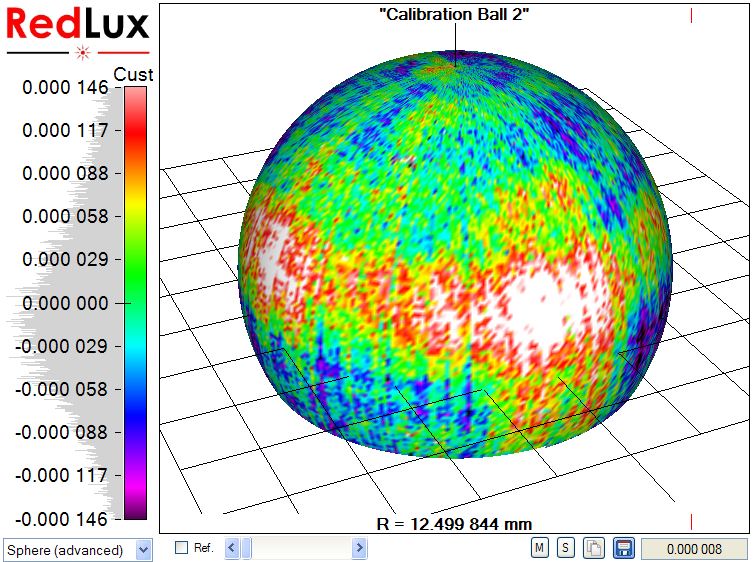
The form error on this ball is negligible for the purpose of machine error assessment and any measurement of this ball will show the machine error. The calibration ball has been measured to assess the errors for sphericity and radius measurements.
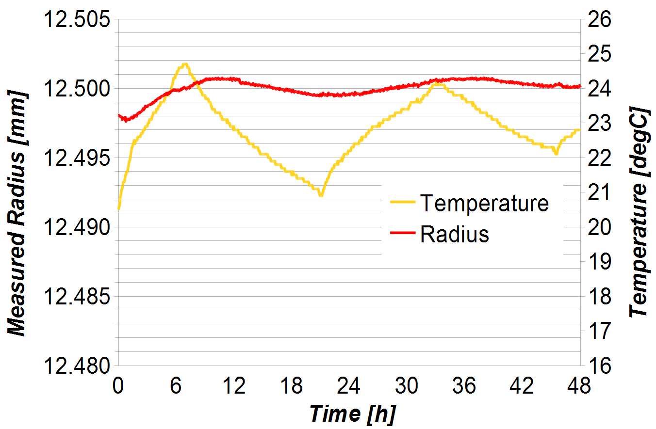
The thermal influence on radius measurements was assessed by repeatedly measuring the calibration ball over a two day period, while ambient temperature varied.
The current standard for volumetric wear assessment on simulator samples is the gravimetric method as introduced above. To compare the Artificial Hip Profiler with the gravimetric method, a test was set up whereby 6 fully finished modular heads were worn and the wear assessed with both techniques. Artificially worn parts were preferred to parts worn in a wear simulator as the latter can easily be contaminated by fluids surrounding the joint, making an accurate weight measurement difficult. Six intact ADEPT (Finsbury Orthopaedics Ltd, Leatherhead, UK) modular head components (42 mm diameter) were measured as detailed below before proceeding. Worn patches were created by polishing the surface with a polishing mop at a given, known position for 1 to 5 minutes using a hand held powered polishing tool.
The procedure below was followed ensuring that traceability was kept at all times.
All measurements were repeated three times for each modular head.
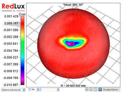
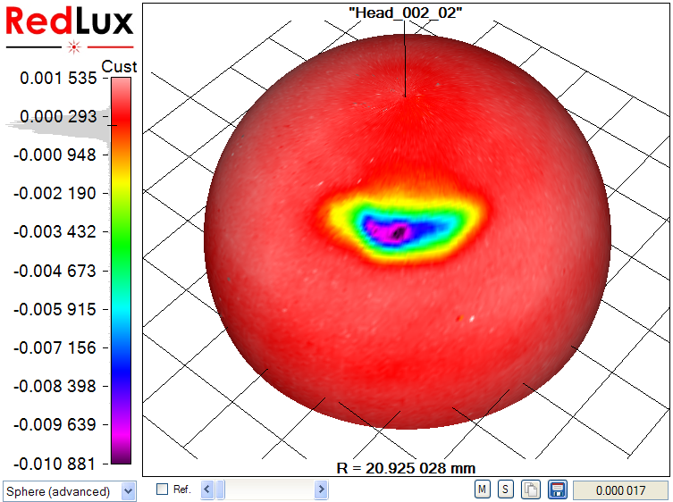
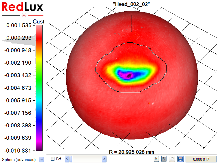
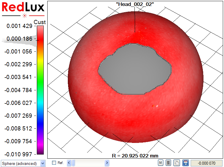
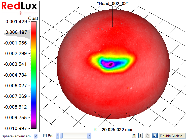
With the Artificial Hip Profiler, the data requires post processing to obtain the volumetric wear from the raw data, as illustrated in Figure 4.
In a first step, a sphere is fitted to the raw data set by linear least-squares sphere fit (a). The result is slightly skewed, as the wear scar impacts the sphere fit. The wear scar is therefore excluded from processing (b, c), and only the original, unworn surface is used to compute the reference sphere. Finally, the previously excluded data points are re-included in the display, showing the wear scar in relation to the unworn bearing surface (d).
 |
 |
|
a) Raw data |
b) Wear scar marked |
 |
 |
| c) Wear scar excluded | d) Wear scar relative to unworn surface |
The wear volume is the difference between the best-fit sphere and the measured data set.
Two measurements were performed on the calibration ball; firstly, a measurement of sphericity and secondly, a measurement of radius over time. This was to establish the base accuracy of measurement.
Figure 5 shows the result of a sphericity measurement on the calibration ball. 95% of the measured points are within 146 nm of the best-fit sphere, showing the measurement error of the system. To achieve this level of accuracy, the system is located on a vibration isolation table and stage errors are compensated for numerically. Temperature drift during measurement is negligible, due to the short measurement time.
To establish the instrument performance versus external temperature, 866 repeat measurements of the calibration ball over a period of 2 days were performed. On the left axis in Figure 6 the measured radius is shown as the red curve, while the right axis shows the ambient temperature with the curve in yellow. The temperature varied by ± 2.1 ºC, while the radius varied by ± 1.6 μm over the same 2 day period. It should be noted that the thermal expansion of the tungsten carbide ball was not taken into account. It is expected that this would have resulted in a slight improvement of the measurement results.
Temperature effects are numerically compensated for and only have a small influence on the measurement of component radius, even in an uncontrolled environment. The influence of temperature on the measurement of sphericity and wear is negligible, because these are measured relative to the best fit sphere. If the radius of a 25 mm head changes by 1 μm due to a temperature change, the linear wear measurement of a wear scar of say 25 μm changes by
25 μm x 1 μm / 25 mm = 1 nm.
On a wear patch of 500 mm2 this causes an error of 0.0005 mm3 and can be neglected.
The following table summarises the results obtained with the benchmark methods and the Artificial Hip Profiler (AHP) for the 6 heads under study, measured three times over two days in a non-temperature controlled environment (average and standard deviation of three samples shown).
|
Component Id |
AHP Measurement time (min and sec) |
Diameter (laser micrometer) mm |
Diameter (AHP) mm |
Linear Wear |
Linear Wear |
Volume Loss |
Volume Loss |
| 1 |
1’53-2’07 |
41.8484 |
41.849089 (0.00083) |
10.3 (0.3) |
10.7 (0.3) |
0.313 (0.006) |
0.280 (0.022) |
| 2 |
1’51-2’06 |
41.8499 |
41.850737 (0.00251) |
23.3 (0.4) |
22.9 (0.3) |
0.600 (0.004) |
0.575 (0.016) |
| 3 |
1’52-2’06 |
41.8477 |
41.849245 (0.00193) |
2.0 (0.1) |
2.6 (0.1) |
0.069 (0.004) |
0.047 (0.005) |
| 4 |
1’51-2’07 |
41.8478 |
41.847964 (0.00036) |
9.3 (0.2) |
11.0 (0.1) |
0.306 (0.005) |
0.293 (0.001) |
| 5 |
1’52-2’07 |
41.8518 |
41.852021 (0.00153) |
11.7 (0.3) |
12.2 (0.2) |
0.404 (0.002) |
0.392 (0.012) |
| 6 |
1’53-2’07 |
41.8453 |
41.846755 (0.00144) |
3.6 (0.1) |
3.9 (0.2) |
0.067 (0.006) |
0.064 (0.003) |
The diameter measurements are in good agreement between laser micrometer and Artificial Hip Profiler, with the variation likely to be caused by temperature variations of the components.
Linear wear measurements are again in very good agreement, with the measurements by the Artificial Hip Profiler being generally larger than those measured with the roundness instrument. The deepest part of the wear scar on these components extends over only one or two millimetres and with the roundness instrument it is difficult to find the exact location of the valley.
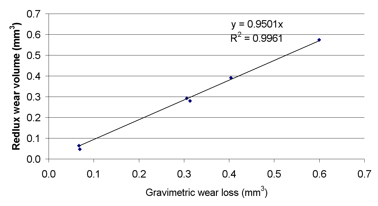
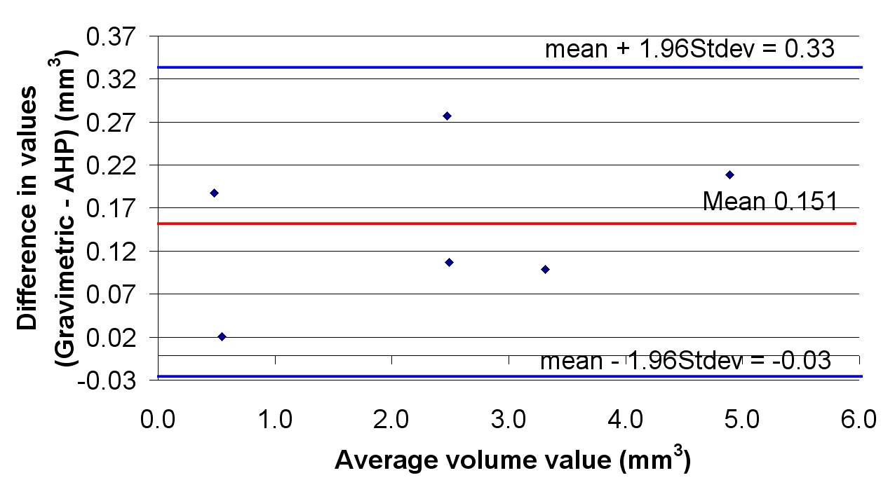
Thirdly, the Artificial Hip Profiler provides comparable results to the gravimetric method. The maximum difference for measured volume loss is 0.033 mm3 Potential sources of errors arise from the volume estimation used in the Artificial Hip Profiler. Despite these, there is a strong agreement between the two techniques, with the AHP providing the advantage of a quick measurement without the need for extensive cleaning.
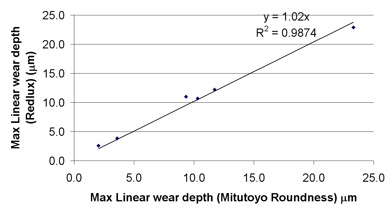
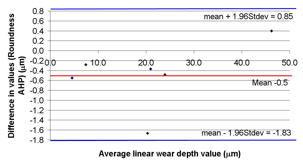
The correlations between the optical and control methods for the measurement of wear are shown in Figure 7. The correlation coefficients were 1.02 and 0.95 for the linear and volumetric wear respectively. The R values were 0.988 and 0.996 respectively. The Bland-Altman plots are shown in Figure 8.
 |
 |
It is expected that these results can be improved upon, when measurements of component form are performed prior to wear and a before/after comparison is carried out. This work is currently under way and subject to a future publication.
The new device can perform the measurement of diameter, linear wear and volumetric wear in a single measurement taking only a few minutes.
In contrast to the gravimetric method, the Artificial Hip Profiler eliminates the need for extensive cleaning of components. It provides information on the wear volume as well as the shape and location of the wear patch and works on both wear simulator samples and retrievals.
In comparison to a roundness instrument, the Artificial Hip Profiler provides a 3D scan of the surface, permitting volumetric wear measurement and geometric information on the wear scar.
The results show a strong correlation to the results obtained using conventional methods.
The Artificial Hip Profiler, based on the chromatically encoded confocal measurement method, had been developed to measure spherical bearing surfaces for total joint replacement with diameter ranging from 28 to 58mm in diameter. It is capable of scanning the parts in a few minutes.
On worn parts, a 3D visualisation of the surface can be obtained, and wear patches of depth as small as a few microns and as high as a few hundred microns can be analysed. The correlation of the results obtained in terms of unworn sphere diameter, linear wear depth and volume wear loss estimation all correlate extremely well with results obtained using benchmark methods, with correlation coefficients of 0.95 and 1.02 and R ratios of 0.986 and 0.996.
The authors would like to thank Dr Bill Walter and Christina Esposito, University of New South Wales (Australia), and Dr Richie Gill, University of Oxford (United Kingdom), for valuable discussions during the preparation of this paper.
Reference List